Raspberry Pi + LED + Photodiode + Fidget Spinner |
Story location: Home / computing / raspberry_pi / |
| 05/Jun/2017 |
Several years ago I had the idea of using a camera or light sensor to measure how fast a hamster runs in a wheel. I never actually did anything about it but I recently saw a fidget spinner in action and decided to measure its speed using LEDs and a photodiode.
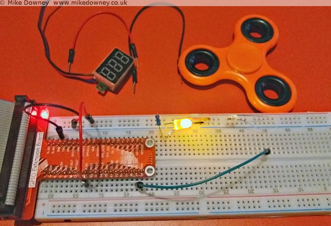
The circuit was incredibly simple. At first I thought I might need to connect the photodiode to an amplifier or schmitt trigger or something like that but when I pointed the LED directly into the photodiode and attached the voltmeter to the latter, the voltage went close to zero when I blocked the light and went over 3v when I let the light through. It looked like I could just connect the photodiode directly to a GPIO pin of the Raspberry Pi to measure when the light path was blocked.
The next step was to write some code to detect when the GPIO pin changed state and to measure the frequency. When I logged into the Pi, I found a script which actually did exactly that. I'm not entirely sure where this came from. I may have adapted it from a C exmaple from the pigpio project but I can't actually remember. It uses NumPy to calculate the average.
Wiring it up
Connecct the LED to the 3.3V output of the Pi, through a 220 ohm resistor. Connect the photodiode 'in reverse': the long leg to GPIO 26 of the Raspberry Pi and the short leg to the 3.3v supply. When the light level is low, the photodiode will act like a normal diode and block the current. When the light level is high, the current will flow and the GPIO pin will detect a 'high' signal.
Results
I fired up the edge.py script, started the figet spinner and lowered it into into the light beam. I had to be careful to avoid it touching the breadboard, the LED or the photodiode so I almost certainly didn't manage to spin it as fast as I could. I ran the script a few times and got numbers between 30-50 Hz. Since the spinner had 3 lobes, this means that it was only spinning between 10 and 15 times per second.
Matt Parker has a video where he uses a spectrum analyser to measure the frequency of the spinner. He uses a compressed air can to reach much higher speeds.
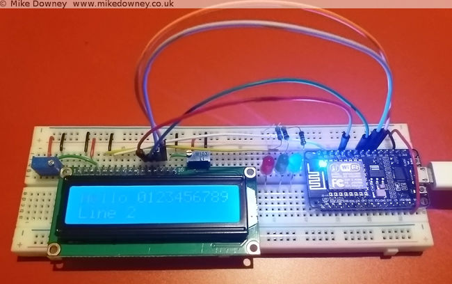
When I bought the electronics starter kit for the Raspberry Pi, it came with a small 16 character by 2 line LCD. I found instructions on the Adafruit website for wiring it up and controlling it. I thought it might also be a useful thing to use with the NodeMCU board so I had a look for any instructions for that.
Unfortunately everything I found was for the I2C version of the display and I've got the plain parallel bus version, so I decided to have a go at wiring it up and programming it myself.
Wiring up the board
The wiring is quite straightforward, although a lot of wires are required. Six GPIO pins are needed at the NodeMCU end, along with power and ground.
Starting with the power pins, connect one of the ground pins from the NodeMCU to the ground rail of the breadboard. The 'Vin' pin supplies 5 volts (if used with a usb connection) so connect a wire from that to the '+' rail of the breadboard.
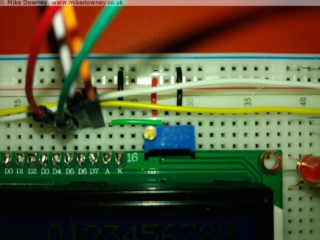
Four data lines are required: D4-D7 on the LCD. To make things easier I connected these to pins 4-7 on the NodeMCU board. The final two connections from the NodeMCU are 'Clock' (called 'E' on the display board) which went to pin 2, and 'RS' which went to pin 1. Data line D0-D3 from the display board are left unconnected.
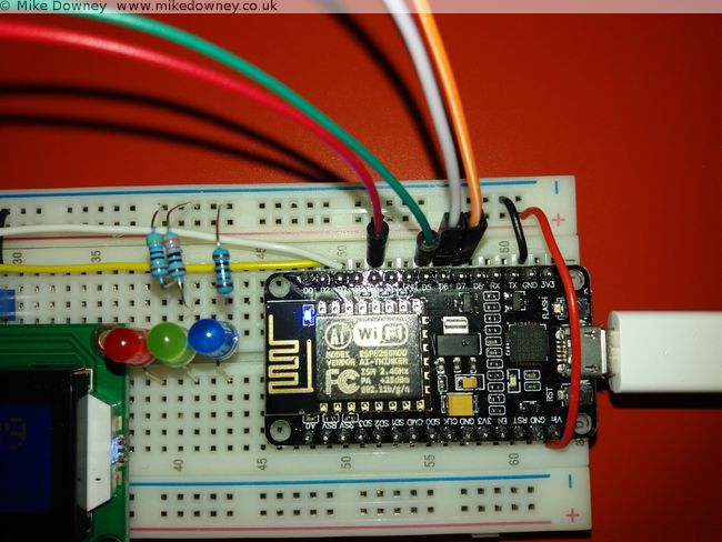
The rest of the pins on the board go to either 0V, 5V or a potentiometer set as a voltage divider (ignore the 3 LEDs in the pictures, they aren't needed here).
Connect the following pins to ground (0V):
- 'RW' (set permanently to Write mode since we aren't reading from the board)
- 'VSS' (the board's ground connection)
- 'K' (the ground connection for the backlight)
- One side of the two potentiometers.
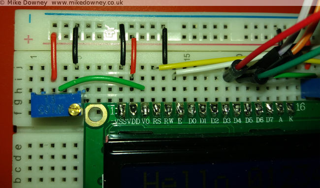
Connect the 'VDD' pin to 5V and also the other side of the two 10K potentiometers. Finally, the 'V0' and 'A' pins can be connected to the centre of the two potentiometers to provied adjustable contrast and backlight.
Programming the board
I based my Lua code on the Python code downloaded from the Adafruit website. Since I was converting the code from one language to another, I read through it carefully to make sure I only converted the bare minimum to get it working.
My first version of the code was little more than a few subroutines to send bytes to the board. While I was reading the NodeMCU Lua FAQ, I noticed that they recommend that code is written to be event driven instead of the more traditional program flow used in scripting. They also state that routines called from an event can only take a maximum of 10 milliseconds to run before they affect background services. After reading that I changed my code to buffer the text and use a timer to check the buffer and send the bytes to the display.
The current version is probably too cautious and sends a byte at a time. It might be more efficient to send a line at a time but that should be easy to change.
The code can be found over on Github. I have decided to put it there since it is easier for me to keep it up to date and easier for anyone else to download.
Using the Raspberry Pi serial port from Java |
Story location: Home / computing / raspberry_pi / |
| 25/Feb/2017 |
A couple of days ago I wrote about connecting the Raspberry Pi to the NodeMCU microprocessor board. I originally used Python since I find that the easiest for testing ideas or simple prototyping. Since I use Java for most of my application programming, I thought I should work out how to do the same thing in Java too.
Luckily there is a Java serial comms library called RxTx which is available precompiled for Debian Linux and can be installed on the Raspberry Pi simply by typing
sudo apt-get install librxtx-java
The jar file is placed in /usr/share/java/RXTXcomm.jar (and doesn't seem to be added automatically to the classpath) so to compile any code, you'll need to use something like
javac -cp /usr/share/java/RXTXcomm.jar:. SerialTest.java
and to run the code you need to reference both the jar and the JNI library, using
java -cp /usr/share/java/RXTXcomm.jar:. -Djava.library.path=/usr/lib/jni SerialTest
The Code
import gnu.io.CommPort;
import gnu.io.CommPortIdentifier;
import gnu.io.SerialPort;

import java.io.*
import java.util.Scanner;

public class SerialTest{

    public static void main(String[] args) throws Exception{
        CommPortIdentifier portIdentifier = CommPortIdentifier.getPortIdentifier("/dev/ttyS0");
        CommPort commPort = portIdentifier.open("Java Serial Test",1000);
        System.out.println("Opened Port");

        SerialPort serialPort = (SerialPort) commPort;
                serialPort.setSerialPortParams(115200,SerialPort.DATABITS_8,SerialPort.STOPBITS_1,SerialPort.PARITY_NONE);

        String[] leds = new String[]{"r","g","b","off"};

                try(BufferedInputStream in = new BufferedInputStream(serialPort.getInputStream());
                BufferedOutputStream out = new BufferedOutputStream(serialPort.getOutputStream());
        Scanner s = new Scanner(in)){

            for(String c : leds){
                out.write(c.getBytes());
                out.flush();
                System.out.println(s.next());
                Thread.sleep(1000);
            }
        }
    }
}
I saved the code as SerialTest.java and compiled it and ran it using the commands above. It expects the serial.lua file to already be running on the NodeMCU board, either by running the python script from last time or by executing
python nodemcu-uploader.py --port /dev/serial0 file do serial.lua
As you can see, the code is much more verbose than the Python version but it gets the job done.
The long awaited Raspberry Pi post: Interfacing with a NodeMCU |
Story location: Home / computing / raspberry_pi / |
| 22/Feb/2017 |
I first used a Raspberry Pi when I was working in Leicester and I bought one for home not long after that. I set it up as a file/media server and it has been sitting in the front room quietly doing its job since then.
Last year I bought a Pi 3 and an electronics starter kit (which consisted of a breadboard, LEDs, switches and various other components) so I could learn how to connect things to the Pi.
A few weeks ago I was given a NodeMCU development board (my friend Tim has already written about some of his experiments with his).
I followed the instructions on flashing the firmware and getting a script running. For some reason the ESPlorer software doesn't seem to behave well on my computer. It usually takes several rounds of restarting/resetting/reconnecting before it will agree to communicate with it. The command line tools have no problems, neither does CoolTerm. After a day when it felt like I was spending half of my time struggling to get ESPlorer to connect properly, I decided to ditch it and use the nodemcu-uploader command line instead.
The first thing I wrote was the Hello World of the microcontroller world: the flashing LEDs. The next stage was to use the serial ports to connect the Raspberry Pi and the NodeMCU together.
Setting up the Raspberry Pi Serial Port
By default, the serial port on the Pi is configured to be used for a serial console , mainly for diagnostics. To use it for other things, you need to disable the console. There are lots of different instructions to do this but for the Pi 3 it boils down to editing the /boot/config.txt file and adding the line
enable_uart=1
followed by editing /boot/cmdline.txt and removing the
console=serial0,115200
entry. After rebooting the Pi, the GPIO pins 14 & 15 should be available for the serial port.
Writing the script for the NodeMCU
I took my flashing LED script and modified it to listen to the serial port. Sending 'r','g' or 'b' will light up the respective LEDs, any other character will turn them off. If the following script is saved as serial.lua, it can be uploaded to the NodeMCU using
python nodemcu-uploader.py -port /dev/serial0 upload serial.lua
as long as the NodeMCU Uploader has been installed first.
-- Listen on the serial port for a colour.
-- Toggle the colour of the LED.

green=2
blue=1
red=3
gpio.mode(red,gpio.OUTPUT)
gpio.mode(green,gpio.OUTPUT)
gpio.mode(blue,gpio.OUTPUT)

-- Start with the LEDs off
gpio.write(red,gpio.LOW)
gpio.write(green,gpio.LOW)
gpio.write(blue,gpio.LOW)

uart.setup(0,115200,8, uart.PARITY_NONE, uart.STOPBITS_1, 1)

uart.on("data",1,
    function(char)
        if char=="r" then
            print("red")
            gpio.write(red,gpio.HIGH)
            gpio.write(green,gpio.LOW)
            gpio.write(blue,gpio.LOW)
        elseif char=="g" then
            print("green")
            gpio.write(red,gpio.LOW)
            gpio.write(green,gpio.HIGH)
            gpio.write(blue,gpio.LOW)
            lighton=2
        elseif char=="b" then
            print("blue")
            gpio.write(red,gpio.LOW)
            gpio.write(green,gpio.LOW)
            gpio.write(blue,gpio.HIGH)
        else
            print("Off")
            gpio.write(red,gpio.LOW)
            gpio.write(green,gpio.LOW)
            gpio.write(blue,gpio.LOW)
        end
    end,0)
The script can be run using
python nodemcu-uploader.py -port /dev/serial0 file do serial.lua
Getting the Pi to talk to the NodeMCU
I connected the RX GPIO pin on the Pi to the TX pin on the NodeMCU, and vice versa. The easiest way of powering the NodeMCU was to use the power out pins from the Pi. I found that connecting the 5V out to Vin on the NodeMCU worked reliably. If I had the Pi plugged into a good quality USB power adaptor then I could sometimes get it to work by connecting one of the 3.3V pins of the Pi to one of the 3.3V pins of the NodeMCU board, but this isn't guaranteed to work.
The script uses the serial port library, which can be installed using
sudo apt-get install python-serial
The Python script is fairly simple and just cycles through the LEDs a few times. The third line runs the lua script, in case it wasn't already running. There isn't a pause between cycling between the LEDs but the serial timeout is set to 1 second and the port.read(100) command attempts to read 100 bytes. Since there should only be the colour names being returned, this automatically adds a 1 second delay. This might not be very good programming practice but it was the easiest way of incorporating reading a variable length response and adding a pause all at once.
import serial

port = serial.Serial("/dev/serial0", baudrate=115200, parity=serial.PARITY_NONE, timeout=1.0)

port.write("dofile('serial.lua')\r\n")

for i in range(1,10):
    for c in ['r','g','b']:
    port.write(c)
        r = port.read(100)
        print(r)
Flashing LEDs
This first demonstration is pretty trivial, although it took a few days of trial and error to get everything working. In due course I'll experiment with connecting different sensors to the Pi and NodeMCU.
I think my next step is to use Java on the Pi to do the same thing. I have had a quick look at Java serial port stuff and it isn't as straightforward as Python but since I do most of my programming in Java these days, it will be useful to know how to do that.
In the early 90s I wrote a Mandelbrot Set generator in 68000 assembly language on the Atari ST. The 68000 processor didn't have any floating point arithmetic so I wrote a set of fixed point arithmetic routines with precision ranging from 16bit, 24bit and 32bit. These all had 8 bits for the integer with the remaining holding the fraction part.
I managed to find a copy of the program and got it to load in an emulator. The Atari takes around 10 seconds to draw, and only uses a 200x200 window. A couple of years ago, I wrote a Java version which works as an ImageJ plugin. This version is much faster (0.07s for a 800x600 image), which works out as 1700x faster than the Atari, despite only being clocked 300x faster. Processor design improvements and hardware floating point probably account for much of this increase.
The atari version can be downloaded here. The ImageJ version is available here (ImageJ and Java8 required - an older version which works with Java6 is also available)
A couple of years ago I wrote an ImageJ plugin to draw the Mandelbrot Set. I recently updated it to make animations (download available here).
To make an animation like the video, use the ImageJ 'polyline' tool to draw a line, with the spline option to smooth the line. Clicking on the Julia Set button will create a set of images which can be aligned using the following script:
var out = "zigzag1/";

run("TIFF Virtual Stack...", "open=[JuliaSet.tif]");
rename("julia");

var frames = nSlices;
var w = getWidth();
var h = getHeight();

run("TIFF Virtual Stack...", "open=[mandelbrot.tif]");
rename("brot");

setBatchMode(true);

for(i=1; i<=frames; i++){
    merge(i);
}

run("Close All");
setBatchMode(true);
print("Finished");
exit;

function merge(i){
imgname = "frame"+i;
newImage(imgname, "RGB black", w*2, h, 1);

selectWindow("julia");
setSlice(i);
run("Select All");
run("Copy");

selectWindow(imgname);
makeRectangle(w, 0, w, h);
run("Paste");

selectWindow("brot");
setSlice(i);
run("Select All");
run("Copy");

selectWindow(imgname);
makeRectangle(0, 0, w, h);
run("Paste");

fn =  out + imgname+".zip";
print(fn);
saveAs("ZIP", fn);
close();
}
The images will be saved in the folder given in the 'out' variable. Although this can be accomplished using the 'Combine' option in the ImageJ stack menu, the script works with virtual stacks so can handle much longer animations.
Here is the ImageJ version of the classic Game of Life which I wrote in an evening, several years ago. I have made a small change since then so the 'Reset' button clears the window and the 'Random' button fills the window with random dots.
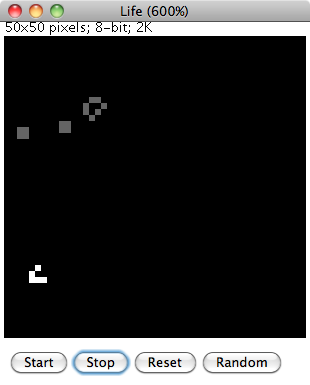
The ImageJ drawing tools can be used to fill in pixels. Clicking on 'Start' will begin the animation. Pixels which have remained unchanged slowly fade to grey while pixels which 'came alive' are in white.
To Install
Download the source code and load into ImageJ or Fiji. Select 'Compile and Run' to start.
The program was cobbled together fairly quickly and ideally would need a bit more work to make it more user-friendly. Any configuration is done by editing the source code and recompiling. The speed of the animation can be changed by altering the value of 'pause' (value in milliseconds). The size of the world is given by the 'width' and 'height' variables. If these are changed then the image window may need to be resized by changing the default magnification in the setMagnification() command.
A few weeks ago I was reading the book The Emperors New Mind by Rodger Penrose and I reached the part where he discusses the Mandelbrot Set. Years ago I used to enjoy exploring this on my computer. I decided to download a mandelbrot program for my mac but couldn't really find one which I liked. This prompted me to have a go at writing one myself. I decided to cheat a little and write it as an ImageJ plugin so I didn't have to handle the display and mouse myself.
I reused some bits of code from a version of Life which I wrote a few years ago and also some code which I developed during my PhD and managed to get a useable plugin up and running that evening. Over the next few days I added a few extra features and made it a bit more useable.
To Install
Click on the download link and save the 'jar' file into the ImageJ or Fiji plugins directory.
To Run
Select 'Mandelbrot' from the 'Plugins' menu. Configuration options are in the 'About Plugins' submenu of the 'Help' menu. After changing any options, the mandelbrot set window will need to be closed and the plugin re-run before any changes will come into effect.
How to Use
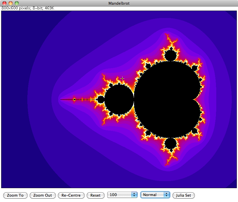
To zoom in or out, use the 'Point' tool of ImageJ to select the new centre and click on either the 'Zoom To' or 'Zoom Out' buttons at the bottom of the window. To pan the view without changing the zoom, select the new centre then click on the 'Re-Centre' button. The 'Reset' button returns the view back to the original zoom.
The number selection box to the right of 'Reset' controls how many calculations are performed before the algorithm decides whether a point belongs to the set or not. Increasing this number will show more detail at the fringes of the set at higher zoom levels.
The Normal/Sqrt/Log selection controls how the colour values are calculated. Initially all values are displayed in greyscale. To display in colour, select one of the ImageJ lookup tables for the required colour scheme.
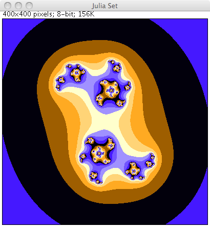
Finally the Julia Set for a particular point can be displayed by selecting a point then clicking on the 'Julia Set' button.
More Details
Further details on the Mandelbrot Set and Julia set can be found in Wikipedia.
I was discussing nursery rhymes and similar childrens songs with Emma and we were talking about how we learned slightly different versions of some songs. Neither of us could remember the full words to the song I'm a little teapot so I decided to look them up. Our tablet computer was nearby so I used that, clicking on the voice search and saying the name of the song.
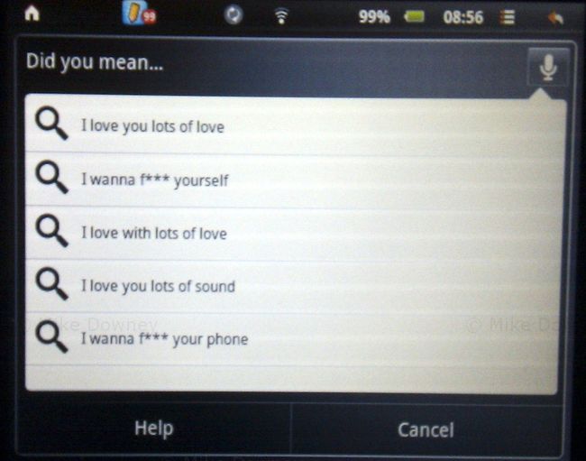
I was a little surprised by some of the suggestions and had to search the old fashioned way, by typing the words instead. When I tried the search using my phone, it correctly recognized what I was saying.
I really have no idea what the computer thought I was saying.
Last year, Emma bought an Advent Vega tablet computer. It uses the same 'Android' operating system as many mobile phones but of course with a much larger screen.
The only real problem with the Vega is that out of the box, it doesn't support the Android Market, which makes it a bit difficult to install applications. We installed an updated version of the software which makes the tablet much more useful. Without the Android Market, you are more or less restricted to web browsing and the built-in applications.
After playing around with it for a few weeks, the tablet ended up in the bottom of a drawer for a few months, unused and ignored. We both had new HTC phones which came with Android, so we could do all the same things on our phones, which also had the advantage of being smaller and more portable.
I recently decided that it would be a good idea to get the tablet up and running again. The main idea was so it could be used to read recipes in the kitchen, to save having to either print out from websites or try to use a laptop in the kitchen. So far I haven't actually used the tablet in the kitchen but it is getting used fairly regularly now.
I don't find it as convenient for web browsing as a full laptop because it is a bit slower and the lack of a full keyboard makes it less useful for using forums etc, but it is perfectly fine for reading ordinary web pages.
We have installed a few applications which get fairly regular use. The one I probably use the most is the Kindle app, which turns the tablet into something very similar to an actual Kindle. You can download books from the Amazon website or install them from elsewhere (such as Project Gutenberg). So far I have read a few freely available, out of copyright, books. I had never read any Charles Dickens books or any of the Sherlock Holmes novels so I decided to give them a go. I decided to start with A Christmas Carol (since it was Christmas at the time), then moved on to The Adventures of Sherlock Holmes and The Hound of the Baskervilles. I am now reading the ebook version of God's Debris, by Scott Adams.
I find reading ebooks or PDFs on the tablet is much easier than on a laptop. The device is much lighter, and the screen is a better shape and size. I have several books queued up ready to read next, including Gulliver's Travels, which I actually downloaded when we first got the tablet but I didn't get around to reading it.
In the last few years, I haven't read as many books as I used to. In the run up to Christmas, I decided that I would spend a bit less time on-line and more time reading, and so far I have been fairly successful. I probably won't be able to keep the pace up and read a book a week but I should be able to catch up on some of the books which I have had for a while but not read yet.